24-hour hotline:+8613662168047
Keyword search: battery plant , lithium battery factory , power bank works , lifepo4 battery mill , lithium forklift battery manufacturer
In recent years, with the increasing development of new energy vehicles, we have actively responded to the call of the country to save energy and reduce emissions, promote the use of new energy, and develop circular economy. Automobile manufacturers have launched their own new energy vehicle products, including pure electric vehicles and hybrid electric vehicles. And with the gradual improvement of technology, it has tended to replace the traditional fuel with electricity as the power source of vehicles. For the design and research of wiring harness in the power battery pack of new energy vehicles, there are various design problems and the birth of new design concepts. The wiring harness in the battery pack is used as the signal transmission of the power battery to realize the effective output of power, and the power consumption and mileage of the power battery in the battery pack are effectively monitored. In the design process, we are also faced with the test of design scheme, layout trend, EMC protection and other aspects.
1、 Harness design scheme analysis
At present, the number and structural form of modules and monomers in the battery pack of new energy vehicles are determined according to the preliminary design objectives. The cooling form of the battery pack is divided into air-cooled and water-cooled battery packs. As for the design of wiring harness inside the battery pack, there are high-voltage wiring harness and low-voltage wiring harness, which are different from the wiring harness of traditional gasoline vehicles. Different forms of wiring harness inside the battery pack adopt different design methods and layout schemes.
1.1 Design scheme of high-voltage harness in battery pack
High voltage harness mainly provides high voltage and strong current power supply for new energy vehicles, so it is particularly important for the design and layout of harness, mainly following the following principles:
1) Harness direction design: the high-voltage harness design adopts the dual-track system. Since the high-voltage has exceeded the safety voltage of the human body, the body cannot be used as the grounding point of the whole vehicle, so the design of the high-voltage harness in the package must strictly implement the dual-track system for the DC high-voltage circuit. The high-voltage harness in the package can be divided into high-voltage total positive and high-voltage total negative.
2) High voltage connector selection: High voltage connector is mainly responsible for the connection and transmission of high voltage and large current, and for the man-machine safety of high voltage circuit. Therefore, at present, high-voltage harness connectors mostly use functions such as high voltage resistance, high waterproof grade, loop interlock, shielding layer connection, etc.
3) Shielding design: shielded high-voltage wire is used, and the shielding mesh is wrapped inside the high-voltage wire., The shielding layer is connected when the connector is connected. Considering the factors of electromagnetic interference, the entire high-voltage harness system is completely covered by shielding layer.
4) HV line layout:
Considering safety and electromagnetic interference, high-voltage wire and low-voltage wire harness shall be arranged separately.
1.2 Design scheme of low-voltage harness in battery pack
1.2.1 According to the working principle and design structure of the battery, the internal harness is divided into:
1) BMU (BMS main board) harness: the main function is responsible for the realization of BMS main control functions such as battery state estimation (SOC SOP SOH, etc.), actuator control, thermal management strategy, high voltage safety, fault diagnosis, etc.
2) LMU (BMS slave board) harness: It is mainly responsible for the collection and monitoring of unit voltage and battery temperature.
3) HCU (BMS high-voltage board) information acquisition harness: high-voltage acquisition, insulation monitoring.
4) High voltage relay coil control harness: responsible for controlling the on-off of high voltage circuit.
5) Current sensor harness: Hall sensor or shunt, mainly responsible for collecting current information.
6) PTC controller: control PTC for heating
7) Solenoid valve: controls the on-off of the air conditioning pipeline of the battery pack.
8) Interlocking plug of each high-voltage connector: high-voltage loop interlocking signal transmission.
The above wiring harness layout is designed separately from the high-voltage wiring harness in the battery pack to effectively avoid EMC interference.
1.2.2 Fixation and buckle selection of low-voltage harness in battery pack:
Due to the limitation of the internal environment and structure of the battery pack, the wiring harness is fixed in a way that is small, easy to assemble and simple to rely on.
1.2.3 Shielding design:
The low-voltage harness is responsible for the function realization of the strong current control unit module and the transmission of relevant signals. In the design and layout scheme of low-voltage harness, the interference protection caused by high-voltage harness shall be considered, and different low-voltage shielded wires shall be used for different signal sources.
High-frequency signal: the harness adopts twisted pair and the shielding layer adopts foil layer shielding.
Low-frequency signal: the harness adopts twisted pair and the shielding layer adopts braid shielding.
1.2.4 Grounding form of shielded conductor:
Single-point grounding: low-frequency signal adopts single-point grounding.
Multi-point grounding: high-frequency signal adopts multi-point grounding.
2、 High and low voltage harness layout scheme
Internal harness layout and design analysis of power battery
Figure 1. Layout of high and low voltage harnesses in the battery pack
In order to avoid the risk of electromagnetic interference caused by high voltage harness when transmitting strong current, which leads to the risk of electromagnetic interference caused by low voltage harness to control unit power supply and signal transmission, our pure electric vehicle power battery pack adopts the layered and parallel design of high voltage harness and low voltage harness, which effectively avoids the interference caused by strong current operation. The layout is shown in Figure 1.
2.1 Layered arrangement: HV harness and LV harness are divided into upper and lower levels. 2.1.1 Layered cabling
In the early layout of the battery pack, the high-voltage power supply and low-voltage signal acquisition of the battery module shall be considered for hierarchical wiring. The series connection between the modules shall ensure that the high-voltage connection line (red in the figure) is under the module, and the low-voltage control wiring (blue in the figure) related to low-voltage signal acquisition is on the upper layer of the module. The layered wiring can effectively protect the EMC interference generated by the operation of high-voltage lines. Ensure the stability of power supply and signal transmission in the battery pack.
2.2 Parallel arrangement form: 2.2.1 The direction is parallel to the internal structure of the battery pack (as shown in Figure 2).
The high voltage wiring of the front-end module and the low voltage wiring of the BMS main board are arranged in parallel to ensure that the high and low voltage harnesses are parallel and not crossed. Effectively protect the EMC interference to the controller when the high-voltage harness works.
Internal harness layout and design analysis of power battery
Figure 2. Module, controller and wiring harness layout in the battery pack
3、 Fixation design of high and low voltage harnesses 3.1 Selection of buckles in the harness battery pack: clip type tie buckle (Figure 3), clip type stud buckle (Figure 4), and strap fixation (Figure 5).
Internal harness layout and design analysis of power battery
Fig. 3 Clamping type tie buckle
Internal harness layout and design analysis of power battery
Figure 4. Clamping stud type buckle
Internal harness layout and design analysis of power battery
Figure 5. Fixing and bundling with ties
3.1.1 The ties in Figure 3 are mainly used for high and low voltage harnesses. They are connected in the plastic air duct at the front and rear sections. The structure is made inside the air duct to fix the harnesses with the clamp type ties. The installation hole is reserved for the air duct body for the fixed assembly of the harness.
3.1.2 The clip stud type clip in Figure 4 is mainly used under the front and rear battery modules, and the fixed stud is welded at the bottom of the sheet metal to fix the harness with a tie.
3.1.3 In Figure 5, the binding wire harness is mainly used for fixing the LMU slave board and HCU signal acquisition wire harness on the upper cover plate of the rear end module.
4、 Design and analysis of high and low voltage harness in battery pack
The high-voltage wiring harness adopts a dual-rail design, connecting the front and rear modules of the battery pack in series, PTC in the battery pack, air-cooled fan, strong current maintenance switch, charging pre-charge circuit, etc. to the principle circuit. The high-voltage connector at the front end of the battery pack provides strong power supply for the whole vehicle. The high-voltage connector is shielded by the plug-in body, and the high-voltage interlock function is added to effectively protect the EMC interference generated by the high-voltage current.
The principle design of the low-voltage harness inside the battery pack is the same as that of the wires and the selection principle of the wires used in the external whole vehicle harness of simultaneous interpreting Tongchuan. The difference is that the internal harness of the battery pack is mainly used for signal acquisition, and the related sensor components are monitored inside the battery pack. At present, high temperature resistant conductors, shielded wires, twisted pairs, etc. are used. Interact all collected information to the BMU (as shown in Figure 6) for power supply, thermal management in the battery pack, heat dissipation in the pack, battery charging and discharging, and other related controls.
Internal harness layout and design analysis of power battery
Figure 6. Schematic design of BMU
4.1 Power distribution scheme for EMC protection of wiring harness in battery pack
Within the scope of the whole vehicle, firstly ensure that the EMC of the parts meets the standard requirements, connect all control units together through wire harness connection, and use the protection method in power distribution
Where, the power supply circuit and the grounding point circuit are arranged in the same connector in the way shown in Figure 7.
Internal harness layout and design analysis of power battery
Figure 7. Power distribution scheme
4.2 Harness design scheme for EMC protection in battery pack
In order to effectively prevent the electromagnetic interference caused by the excessive current of the harness, the twisted pair is generally used in the selection of the harness material, and the twisted pair loop is arranged at the outermost side of other harnesses. In the aspect of high-frequency signals, shielded twisted pair can be used.
90% of the conducted emission in the vehicle harness is related to the power line, so the following aspects should be paid attention to when evaluating and designing the harness
1) For the part of switching power supply, loop control is considered in the design.
2) Sensitive signals are transmitted by shielded cables, and the shielding layer is subject to 360 ° overlap.
3) The signal cable shall be far away from high-voltage network and strong interference sources, and shall be reasonably tightly coupled with the ground.
4) Take measures to ground the filter to reduce the lead inductance.
5) Sufficient signal-to-ground ratio shall be ensured in the cable, and reasonable arrangement and configuration shall be made.
4.3 Design analysis of power line conduction transient immunity protection
At the initial stage of design, the power line conduction transient immunity should also consider the protection design of surge and pulse when the new energy vehicles work at high voltage and low voltage.
4.4 Pulse interference protection
In the process of opening or closing the switch relay and fuse in the battery pack, due to the interference pulse generated by the arc, it is also necessary to carry out the protection considered at the initial stage of harness design.
Summary
Through the rational design and layout of the harness in the early stage of the design and development of the harness in the new energy battery pack, as well as the key consideration of the EMC protection in the design stage of the high and low voltage principle in the battery pack, the interference generated during the operation of the strong current harness is effectively avoided, and the harness layout scheme and EMC design are continuously optimized through the carrying platform and the actual vehicle certification. The current wiring harness layout and various EMC protection schemes and measures have been fully verified and recognized in the batch production project.

Lithium ForkLift Batteries ,Ensure Quality
Our lithium battery production line has a complete and scientific quality management system
Ensure the product quality of lithium batteries
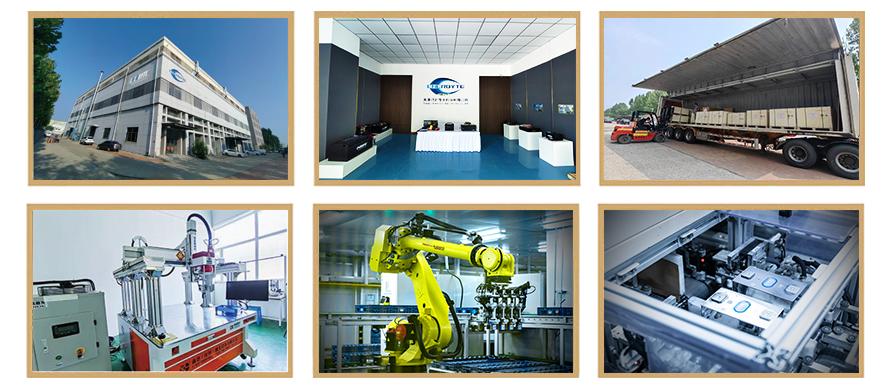
Years of experience in producing lithium forklift batteries
Focus on the production of lithium batteries
WE PROMISE TO MAKE EVERY LITHIUM BATTERY WELL
We have a comprehensive explanation of lithium batteries
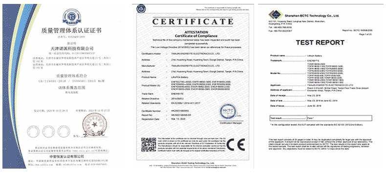
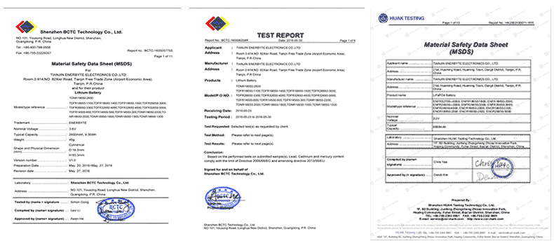
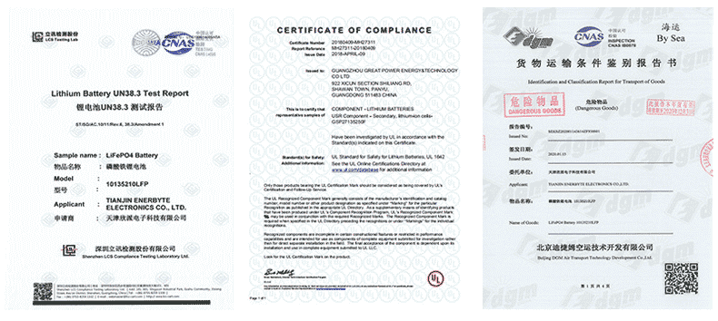
QUALIFICATION CERTIFICATE
THE QUALITY OF COMPLIANCE PROVIDES GUARANTEE FOR CUSTOMERS
MULTIPLE QUALIFICATION CERTIFICATES TO ENSURE STABLE PRODUCT QUALITY
Providing customers with professional and assured products is the guarantee of our continuous progress.
Applicable brands of our products

| Linde Lithium Forklift Battery | Toyota Lithium Forklift Battery | hyster Lithium Forklift Battery |
| jung Lithium Forklift Battery | enrich Lithium Forklift Battery | hyundai Lithium Forklift Battery |
| still Lithium Forklift Battery | heli Lithium Forklift Battery | hangcha Lithium Forklift Battery |

 Service hotline