24-hour hotline:+8613662168047
Keyword search: battery plant , lithium battery factory , power bank works , lifepo4 battery mill , lithium forklift battery manufacturer
As for battery cells, the higher the rate of external force impact, the smaller the force value they can withstand; After grouping, the battery cells can withstand greater impact deformation, what are these phenomena.
This article is 19500 words and is expected to be read in 49 minutes.
(1)
The use of external forces can cause damage to the mechanical structure of batteries, leading to thermal runaway or even explosion accidents. This is a possible scenario for electric vehicles as road vehicles to encounter traffic accidents. MIT researchers have sorted out the changes that occur in lithium-ion batteries during collisions at large, medium, and small scales. The paper "Areviewofsafety-focused mechanical modeling of commercialism on batteries" was published in the Journal of Power in December 2017, by JunerZhu et al.
1. Introduction: Research on the mechanical properties of LIBs at multiple scales
The launch of ChevroBolt and Tesla Model 3 in 2017 marked a new era in the automotive industry. The distance between two cars charging at once exceeds 200 miles, and it has a price range that an ordinary person can afford. According to a comprehensive report by UBS, the time for gasoline and electric vehicle costs to be on par will be 2-3 years earlier than originally expected. This trend is mainly attributed to the progress brought about by the simultaneous decrease in energy capacity and battery pack prices of lithium-ion batteries.
It is expected that the annual production of Tesla Model 3 will reach 500000 units, and General Motors' Bolt production is slightly lower than Tesla's. The all-new Nissan Leaf has a range of 150-200 miles and will be launched in 2018. In short, the total stock of EVs has exceeded one million units in 2016 and has now reached a new starting point of qualitative change. The International Energy Agency predicts that by 2025, there will be up to 100 million cars on global roads. With such a large quantity, statistical rules will inevitably come into play, and electric vehicles will encounter the same accident rate as traditional fuel vehicles. The question that must be answered is, what new problems will electric vehicles encounter that gasoline vehicles do not have?
Figure 1. The study of the mechanical properties of LIBs involves multiple scales and disciplines, and various models have been proposed to characterize the mechanical behavior of LIBs at each length scale.
It is widely recognized that if the battery pack is torn or damaged in an accident, there may be thermal runaway, fire, and explosion of the battery. There have been several accidents, which can almost be said to be widely known. The Tesla Model S caught fire after colliding with an obstacle, indicating that there are indeed additional dangers involved in driving an electric vehicle. With the continuous increase in the capacity of lithium-ion batteries and battery packs, more energy can be released in a short period of time in car accidents, making the danger of accidents also increasing. The automotive industry, battery manufacturers, regulatory agencies such as NHTSA in the United States, BAM in Germany, and the insurance industry should be prepared to address this prominent issue.
This article aims to review the research progress on the issue of batteries bearing mechanical loads in collision events. Although there have been many studies on battery electrochemistry and thermal management, the research on battery response and failure caused by mechanical loads lags far behind current research. Prior to this, safety issues were primarily exposed through the media, brought into the public eye, and had a social impact, but the importance remained at the stage of discussion. In the soon to come future, safety issues have already had a tangible impact on social, economic, and personal life. The collision safety of lithium-ion batteries should receive appropriate attention.
There are many literature related to safety issues such as preventing thermal overheating and overcharging of batteries, and the focus of this review is on the intrusion of rigid objects into battery units, modules, and battery packs. The battery pack is usually placed in the least deformable part of the car. However, mechanical loads may still be transmitted to the battery pack in collision accidents, especially in side impacts, road debris impacts, and small overlap collision tests. Due to the impact force caused by deceleration during the collision, external insulation may also be damaged. These types of fault modes are highly dependent on design, and electrical system design has a greater responsibility to consider handling relevant situations, while mechanical parts take the second place.
The research on battery safety involves multiple scales. Therefore, this article is divided into three parts, which respectively discuss the safety issues of batteries under specific scale conditions, and based on this, explain the direction of further research. The article presents important findings from research over the past decade in a simple and understandable table format, including typical parameters of commercial batteries with different shapes, and different types of cells assigned different shape factors. The literature that focuses on review should have two characteristics. Firstly, the literature should explain the specific process and principle of battery cell damage and failure, as well as the important influencing factors that lead to short circuits and thermal runaway; Secondly, it involves computer simulation models, detailing what testing parameters should be considered in finite element simulation model calculations.
2. Part 1: Microscale and Mesoscale: Constitutive Models of Battery Components
At present, the coiled cell (or electrode stack) of commercial lithium-ion batteries on the market is a multi-layer structure (see Figure 2a), where a repeatable unit consists of a cathode, an anode, and a two-layer separator.
Table 1
The cathode collector is made of aluminum foil, and its two sides are coated with active materials and adhesives. Similarly, the anode is composed of copper foil coated with graphite (or silicon) particles. All components are immersed in electrolyte and wrapped in aluminum-plastic film or steel shell. The chemical composition and materials of each component may vary among different battery manufacturers, but the basic structure of this repeatable component is almost identical. Figures 2 (b) - (c) show the intersection of commercial lithium-ion battery modules with NMC (nickel manganese cobalt) cathode, graphite anode, and microporous polypropylene separator. Table 1 qualitatively describes the mechanical characteristics of each component. In the remaining parts of this section, the mechanical characteristics of all components will be detailed.
The term shape factor distinguishes soft pack cells, square cells, elliptical cells, and cylindrical cells. The size of the soft pack battery can range from small batteries in mobile phones to large secondary batteries in EV applications. For example, the most common cylindrical battery used in the Tesla Model S, the 18650, has a diameter of 18 millimeters and a length of 65 millimeters. Tesla Model 3 uses a larger cylinder with 2170 units. Therefore, the size of the battery cell is not micro. The microscale and mesoscale titles refer to individual components and complex structures of coatings and membranes with very small thicknesses.
2.1 Collector
The collector for commercial lithium-ion batteries is metal foil - aluminum for the cathode and copper for the anode. The thickness of the foil is about 10-25μ M. Copper foil is usually slightly thinner than aluminum foil. Both materials exhibit typical elastic-plastic mechanical properties of metallic materials. Table 2 shows the elastic modulus E and Poisson's ratioν of aluminum and copper;, The plastic properties are defined by the coefficients of anisotropy and hardening curves.
Figure 2. (a) Cross section of reproducible units (RVE) and components of lithium-ion batteries; (b) NMC cathode; (c) Graphite anode and; (d) Polypropylene diaphragm (microporous polypropylene).
Table 2, Elastoplastic parameters of collector foil and 18650 cell steel shell body
2.1.1 Plastic anisotropy
During the manufacturing process, thin metal foil undergoes multiple rolling operations, introducing a certain amount of plastic anisotropy into the material. There are two concepts to quantify this attribute, the first being the ratio of yield stress in different directions, which indicates the anisotropy of material strength. According to the tensile test results of the current collector, the difference in yield stress in the machine direction (MD, 0), vertical direction (TD, 90), and diagonal direction (DD, 45) can be almost negligible (see Figure 3a).
The second concept describing the anisotropy of plastic flow in thin plates is defined by the Lankfordr value, which is defined as:
Among them,ε P andε P is the transverse plastic tension and through thickness plastic stress when the sample is loaded in the x1 direction.
Materials are incompressible during plastic deformation. In order to deform the material during tensile testing, the width or thickness of the sample must be changed. Physically, the Lankford parameter tells us the ratio between these two deformations. Regarding isotropic materials, the strain distribution of width and thickness is the same, and rL=1. The determination of the Rankford r value requires a complete full range stress measurement, which is typically accomplished using the Digital Image Correlation (DIC) method. Figure 3c shows the speckle pattern on the dog bone sample and the virtual cross on the tensor. Figure 3b illustratesε 22-ε The curves of the same aluminum foil in three directions in 33 are commercial battery collectors, similar to those in Figure 3A, used as collectors for commercial LIBs. The r value results for this material are 0.2 (MD), 1.5 (DD), and 1.1 (TD), indicating a very significant anisotropy (see Table 2).
In summary, existing test data on collector metal foils indicate that they are almost isotropic in material strength, but highly anisotropic in terms of elastic-plastic flow. Describing anisotropy solely based on the stress-strain curve and ignoring the value of r can greatly affect the distribution of plastic strain is not sufficient. It should also be pointed out that precise measurement of stress-strain curves and Rankford r values requires the sophisticated design of the testing device. The biggest challenge is how to align the specimen without causing edge fracture, wrinkling, and buckling, which is very common with thin films (large length/thickness ratio). One way to overcome this difficulty is through microscopic testing, for which the length and width of the specimen are designed to be of the same order of magnitude as the thickness. Figure 3d shows the loading device for micro testing used in battery research.
In order to mathematically model plastic anisotropy, the Hill48 model is the simplest and most popular model in the field of metal forming. The yield function is given by the following equation:
Among them,σ Ij is the stress component, with six calibration coefficients from F to N, andσ Y (ε p) describes the strain hardening of a material. There are other anisotropic yield functions that can be used for modeling current collectors, such as the YLD series.
2.1.2 Strain hardening
According to the test results of aluminum foil and copper foil, they both have relatively low hardening rates dσ Y/dε P. In other words, the hardening curveσ Y (ε p) tends to flatten with the increase of plastic strain (refer to A in Figure 3). The Voce reinforcement method can effectively capture this special feature,
Among them,σ 0, Q andβ There are three calibration parameters. Other hardening laws, such as Swift's law with the meaning of a power function
, more suitable for describing higher hardening rates. Typical values of parametersσ 0, Q, andβ Given in Table 2. In order to improve the accuracy of characterization, two hardening laws can be combined using a weighted coefficient.
2.1.3 Tough fracture
The fracture of aluminum foil and copper foil is caused by large plastic deformation, during which plastic strain rapidly increases but flow stress remains relatively stable. The current fracture behavior of current collectors belongs to the category of ductile materials, so suitable strain failure criteria can be used to describe it. The simplest strain based ductile fracture criterion is a constant equivalent plastic strain, where fracture is assumed to occur in a material where the equivalent plastic strain reaches a critical value. This is a profound simplification, as experiments have shown that crack strain depends on the stress state. Some metal materials can withstand significant deformation under compression, but are prone to failure under tension. Table 2 lists the fracture strains of commercial LIB aluminum and copper foils under tension, biaxial tension, and plane strain. A significant difference can be observed from the numerical values, which have been proven to follow the Mohr Coulomb (MC) fracture model.
Among them,σ 1 andσ 3 is the maximum and minimum principal stresses, and specifically, c1 and c2 are two unknown coefficients that control the fracture trajectory. The MC criterion can be transformed from the principal stress space to the (σ,η,θ) space. Equivalent stress can be represented by stress invariants,
Among them,η Andθ The parameters of triaxiality and load angle have the following meanings:
Figure 3. Test results and metal component settings (a) Engineering stress-strain curves of aluminum foil used as a cathode collector in three directions (MD, TD, and DD), (b) Transverse plastic strain axial plastic strain of aluminum foil tensile test, (c) Explanation of transverse and axial strain on dog bone samples with spots, (d) Loading device for micro testing, (e) Sample design in mechanical performance study of 18650 cylindrical battery shell, (f) Plane strain samples of battery components.
And the hardening curveσ (ε p) For example, power-law equations
The failure plastic stress can be obtained.
Among them, a and n are the results of fitting power function data. The MC model can be easily calibrated using the values listed in Table 2. In a simplified way, two fracture constants can be determined through DIC strain measurements in plane strain and axisymmetric impact tests. This calibration technique has been developed by our research team and has been demonstrated in previous publications.
2.1.4 Strain rate dependence
Many studies have shown that the strain rate sensitivity of aluminum and copper has been decreasing. Bonatti, Mohr, Luo, and Jiang conducted high strain rate tests on thin current collecting foils. As the strain rate (or loading speed in the test) increases, the strength of the two foils significantly increases. This strain rate dependent trend can be described using the Cowper Symonds function or the Johnson Cook model as noted.
Among them,σ 0 is the quasi-static yield stress,
It is the reference strain rate, and C is the strain rate dependence coefficient, which can be obtained from dynamic testing.
Although this trend is a non monotonic function of strain rate, the tensile failure of the two collector foils is also related to strain rate. To draw a conclusion on the dependence of tensile failure on strain rate, there is still very little dynamic testing data available in public information.

Lithium ForkLift Batteries ,Ensure Quality
Our lithium battery production line has a complete and scientific quality management system
Ensure the product quality of lithium batteries
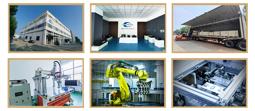
Years of experience in producing lithium forklift batteries
Focus on the production of lithium batteries
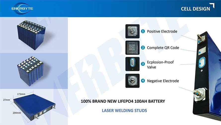
WE PROMISE TO MAKE EVERY LITHIUM BATTERY WELL
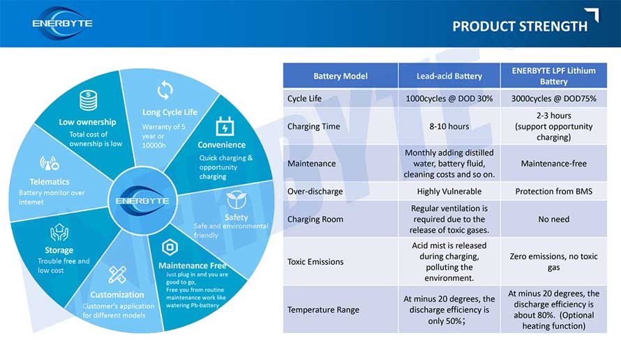
We have a comprehensive explanation of lithium batteries
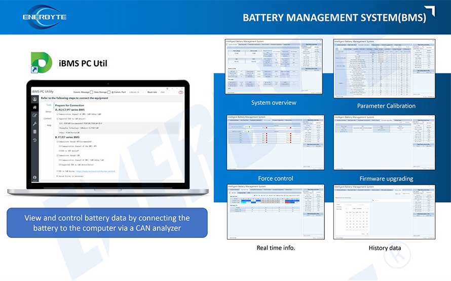
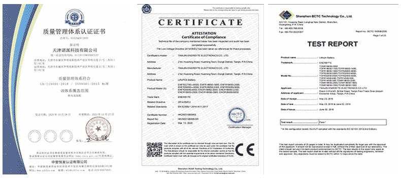
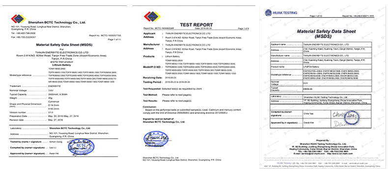
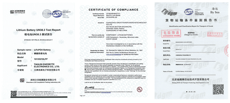
QUALIFICATION CERTIFICATE
THE QUALITY OF COMPLIANCE PROVIDES GUARANTEE FOR CUSTOMERS
MULTIPLE QUALIFICATION CERTIFICATES TO ENSURE STABLE PRODUCT QUALITY
Providing customers with professional and assured products is the guarantee of our continuous progress.

Applicable brands of our products

| Linde Lithium Forklift Battery | Toyota Lithium Forklift Battery | hyster Lithium Forklift Battery |
| jung Lithium Forklift Battery | enrich Lithium Forklift Battery | hyundai Lithium Forklift Battery |
| still Lithium Forklift Battery | heli Lithium Forklift Battery | hangcha Lithium Forklift Battery |

 Service hotline