24-hour hotline:+8613662168047
Keyword search: battery plant , lithium battery factory , power bank works , lifepo4 battery mill , lithium forklift battery manufacturer
1、 Basic Introduction
1、 Squeeze coating type
Regarding extrusion coating, I understand it as applying fluid through a coating head with a special flow channel to a moving substrate.
According to the distance between the coating head and the substrate and the fluid morphology formed between the coating head and the substrate, it can be divided into slot coating and extrusion coating, as shown in the following figure. The important difference between the two lies in whether the fluid wets the lips, with the former wetting the lips and the latter not. The coating process for lithium-ion power lithium-ion batteries uses a slit extrusion coating (SoltCoating).
The important difference between the two lies in whether the fluid wets the lips, with the former wetting the lips and the latter not. The coating process for lithium-ion power lithium-ion batteries adopts a slit extrusion coating (SoltCoating), and the coating system
2、 Introduction to the principle of slit extrusion coating
The two-dimensional schematic diagram of the flow distribution of slit extrusion coating is as follows: The image is from an article by Professor Marcio titled "Fundamentals of SlotCoating Process"
The important factors that determine the coating quality include: the gap between the coating head and the substrate, flow rate, substrate speed, coating head structure, fluid characteristics, etc.
According to the approximate lubrication model of Aikut flow between parallel plates (refer to the Engineering Mechanics Teaching Base of Shanghai Jiaotong University to find fluid mechanics teaching resources for in-depth understanding) and Prof.Marcio, the thickness t formula can be obtained as follows:
It is known that the coating thickness is related to the gap between the coating head and the substrate, fluid viscosity, substrate speed, coating head lip size, fluid and external pressure. From the formula, it can be seen that the gap between the coating head and the substrate is a mechanical fit, the fluid viscosity is related to the incoming slurry, the substrate speed is controlled by the motor, and the lip size of the coating head is determined by the coating head. The above factors are relatively easy to ensure consistency, and the uniformity of coating quality and thickness is highlighted by the fluid and external pressure. The external pressure is generally indoor normal pressure, so the pressure uniformity in the lip and outlet of the coating head is particularly important. The uniformity of pressure distribution inside and outside the lip of the coating head is closely related to the stability of the feeding system and the structure of the coating head.
2、 Introduction to the Structure of Squeeze Coating Head
The structure of the coating head is actually relatively simple, which mainly includes three parts: upper mold, lower mold, and gasket. The lower film has special cavities (such as gradient, hanger, single cavity, and double cavity, etc.), and the upper mold is relatively simple. The gasket is located between the upper and lower molds and can be selected according to different coating forms (such as zebra crossing, full coating, etc.). The following picture shows a coating head mold from Mitsubishi.
2、 Slurry Properties
1、 Slurry composition
The slurry for lithium-ion power lithium-ion batteries is basically composed of active substances, conductive agents, binders, and solvents, as shown in the following figure
2、 Slurry characteristics
As an incoming material in the coating process, the characteristics of the slurry directly affect the coating quality. Through the composition of the slurry, we can understand that it belongs to the solid-liquid two-phase fluid. The important control points for slurry quality in production include viscosity, solid content, density, fineness, and pH value. The uniformity and consistency of the slurry are crucial for the coating process, and testing the uniformity and consistency of the slurry can be obtained by detecting the quality control points of the slurry in different areas.
Since the viscosity of slurry is related to temperature, mixing speed, settling time, etc., according to the meaning of Newtonian fluid and non-Newtonian fluid, we classify slurry as non-Newtonian fluid. After the slurry is stirred relatively evenly, as the stirring time increases, the viscosity of the slurry gradually decreases and finally approaches a stable value. According to relevant literature, there is a phenomenon of shear dilution in the slurry of lithium-ion batteries, where the viscosity decreases with the increase of shear rate in the ratio and homogeneous state. To sum up, we regard the lithium-ion battery slurry as a non-Newtonian fluid with shear dilution. Due to different materials, ratios, and homogenization conditions, the fluid characteristics of the slurry vary under different conditions. This article only introduces the fluid characteristics of the slurry under general and relatively uniform conditions.
Densityρ: The density of lithium-ion battery slurry is generally between 1400~2000kg/m³
Viscosityμ: The viscosity of lithium-ion battery slurry is generally controlled at 1-10Pas according to different process conditions
On the basis of the above, we have already understood the structure of the coating head. Due to the important concern about the flow field state inside the coating die in this article, only a liquid model of the flow channel is established.
Users can model through third-party 3D software and then export STP or X_ T General format, and then import the geometric modeling of slurry fluid through importAssembly.
1) Establish geometric modeling
Create WithCFDModel and click on File&rar; Import→ Aseembly, select the exported stpx_ The model is established as follows:
2) Create Material Properties
Due to the establishment of the model in this article, mm is used and the unit is unified in mm.
Slurry density 1.7e-9tone/mm³, The viscosity is 1500cps, which is 1.5e-6MPas. Assign the above material properties to the geometric modeling.
3) Create Assembly Body
Although the geometric modeling imported from the assembly is recognized as an assembly by the system, you need to switch to the AssemblyModel to establish the assembly.
4) Meshing
This article can use segmentation tools to segment the model, using structured grids, swept grids, and bottom-up grid division to perform hexahedral Hex grid division on geometry. To save grid division time and computational time, this article uses tetrahedral Tet fluid unit FC3D4. By controlling the grid density through edge layout, the grid division results are as follows:
5) Create Fluid Analysis Step
Enter StepModule and create a flow analysis step, TimePeriod: 1, Initialtime measurement: 0.001, TubulenceModel: None. The choice of time increment here is related to the quality of grid division and the size of load. Considering the high viscosity of the slurry, narrow extrusion gap, and low speed, we choose not to use the Reynolds model.
Edit Analysis Step dialog box
6) Create boundary conditions and loads
There are three important boundary conditions and loads. For specific operations, please refer to the previous article "ABAQUS/CFD Basic Simple Knowledge and Cases".
① Boundary condition for inlet velocity, with a velocity of 0.5mm/s
② Outlet pressure boundary condition, 0MPa
③ Fluid prevention boundary conditions, no sliding (inlet and outlet)
7) Create a task and submit it.
This step is the same as the previous case analysis step. After submitting the task, task operation monitoring can be carried out. After completion, click on Result to automatically import the running results and enter the Visualization Module.
8) Post processing
The pressure distribution of the flow field inside the coating head can be viewed through the post-processing function
Velocity distribution
3、 Simulation Analysis of Coating External Flow Field
The important aspect of this section is to simulate and analyze the coating external flow field through ABAQUS/Explicit's CEL algorithm, and obtain the process from coating initiation to stability. Users can view the effects of feeding speed, substrate speed, coating viscosity, etc. on coating thickness according to the tutorial.
1、 Slit extrusion coating model
The two-dimensional schematic diagram of the slit extrusion coating is as follows:
2、 Abaqus algorithm selection
The important methods that Abaqus can use for fluid analysis are CEL (Coupled Eulerian Lagrangian) Euler coupling algorithm, CFD (Computational Fluid Dynamics) computational fluid dynamics and SPH (Smooth Particle Hydrodynamics) smooth particle hydrodynamics. For the scope of use and comparison of the three, users can search on Baidu to view the article 'Comparison of CEL, CFD, and SPHinAbaqus'.
Both CEL and CFD use a fixed grid node algorithm for fluid material flow, as CEL can clearly display the free surface of the fluid material, while Abaqus/CFD cannot. Therefore, this paper chooses the AbaqusCEL method. In addition, the subsequent versions of Abaqus/CAE will no longer have CFD modules. The CFD module has been integrated into 3DEXPERIENCEr2017, and it is believed that the VOF model similar to FLUENT will be improved in the future to be able to add fluids to the CFD module.
3、 Abaqus simulation application
1. Establish geometric modeling of assembly and assembly.
Establish an ExolicitModel. Click to open Abaqus/CAE and select WithStandard/ExplicitModel.
Create the following parts: fluid region geometry components, inlet velocity extrusion components, and coating substrate components. Due to the inability to select continuous velocity supply conditions for the fluid material inlet under the CEL algorithm in display dynamics analysis, this article adds a new inlet area and adds a piston like push block to supply velocity inlet conditions. The assembly model is as follows:
remarks:
1) Due to the use of the CEL algorithm, the components used need to be set to the Eulerian type, and 3D must be selected, as shown in the following figure,
2) To simplify the model to 2D, we established the component process and set the thickness to 1. Other models are selected as discrete rigid bodies, as shown in the following figure
3) During the assembly process, the established discrete rigid body solid components cannot be directly added to the assembly body. To do so, select the rigid body components in the PartModule and click on Shape&arr from the menu bar; Shell→ FromSolid, convert it to a shell.
4) Select an independent mesh form during the process of creating assembly entities.
2. Establish material properties
Establish three properties for the slurry material: density, viscosity, and eos (equationsofstate). In the Explicit model, it is necessary to use the equation of state Us-Up to create materials for fluid dynamics,
For other methods and theories of using state equations, users can refer to the Abaqus manual. The density is set to 1000 and the face is set to 5000. After establishing the material, establish the cross-sectional attributes, and then assign the interface attributes to the geometric components of the fluid region.
3. Create analysis steps and set output results.
Switch to StepModule, create a new analysis step, display dynamics, set Time to 20s, and leave everything else unchanged. The creation result is shown in the following figure.
Create geometric fraction EVF display for fluid regions, as well as displacement output for push blocks and components.
4. Create contact characteristics and reference constraints
Establish the TangentialBehavior contact characteristics, select Penalty (penalty function) for the friction equation, and set the coefficient to 10. Due to the inability of the material to establish the bonding properties between the material and the substrate, this article chooses the Penalty contact characteristics to establish the adhesion effect between the fluid material and the coated substrate. The relevant theories can be found in the Abaqus/CAEUser's Guide under Abaqusdocumentation.
Create test points for the entrance velocity pushing component and establish rigid constraints between the points and the component. As shown in the following figure. Similarly, establish reference points and rigid constraints for coated substrate components.
5. Meshing
By using segmentation tools to perform geometric segmentation on the geometric components of the fluid region, a structured mesh partitioning method can be used. The mesh partitioning results are as follows, and the mesh type of the fluid region geometry is EC3D8R.
6. Create loads and boundary conditions
1) Create boundary conditions for coating substrates
Establish displacement constraints other than the direction of motion
Creating velocity boundary conditions for coating substrates
2) Similarly, create boundary conditions for the entrance velocity pushing component, establish displacement constraints and velocity boundary conditions.
The velocity boundary conditions are as follows
3) Create boundary conditions for fluid region geometry.
Set the initial velocity boundary in the Z direction for both inner and outer surfaces
Set the initial velocity boundary in the X direction on both sides of the entrance, as shown in the following figure
Set the initial velocity boundary condition in the Y direction at the outlet of the coating head, as shown in the following figure
4) Create a pre meaning field Materialassignment, where the pink area is the initial fluid filled area and the Void is zero, indicating complete material filling.
7. Create analysis tasks, submit, and post process.
After creating a task and submitting it, you can view EVF, Void/Materialvolumefractioninelement (Eulerrian). Click on the cloud image to display, and the results are as follows, with the red area showing the fluid.

Lithium ForkLift Batteries ,Ensure Quality
Our lithium battery production line has a complete and scientific quality management system
Ensure the product quality of lithium batteries
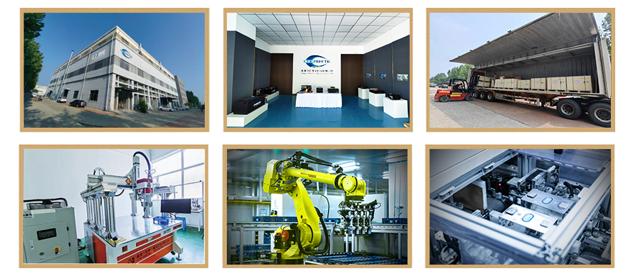
Years of experience in producing lithium forklift batteries
Focus on the production of lithium batteries

WE PROMISE TO MAKE EVERY LITHIUM BATTERY WELL
We have a comprehensive explanation of lithium batteries
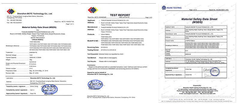
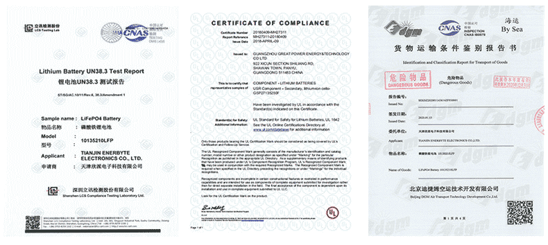
QUALIFICATION CERTIFICATE
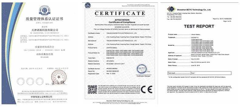
THE QUALITY OF COMPLIANCE PROVIDES GUARANTEE FOR CUSTOMERS
MULTIPLE QUALIFICATION CERTIFICATES TO ENSURE STABLE PRODUCT QUALITY
Providing customers with professional and assured products is the guarantee of our continuous progress.
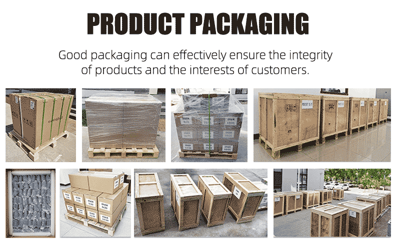
Applicable brands of our products

| Linde Lithium Forklift Battery | Toyota Lithium Forklift Battery | hyster Lithium Forklift Battery |
| jung Lithium Forklift Battery | enrich Lithium Forklift Battery | hyundai Lithium Forklift Battery |
| still Lithium Forklift Battery | heli Lithium Forklift Battery | hangcha Lithium Forklift Battery |

 Service hotline